
This page provides an overview of the new book from Keysight: Engineering for Advanced Radar and Electromagnetic Spectrum Operations. This 315 page book is divided into 28 chapters over six sections. Scroll down for the titles and introductions.
Video demonstrations are linked within each section, with previews here:

Engineering for Advanced Radar and Electromagnetic Spectrum Operations
Would you like to receive further information, request a demonstration or have one of our applications experts discuss your specific needs?
Complete the form and a Keysight representative will be in contact with you shortly.
Section 1: Prepare for a New Era of Security Threats
Chapter 1 Introduction & Evolving Challenges in Radar and EW
Overview and a broader landscape of evolving EW technology and Electromagnetic spectrum operations. Various types of EW threats, cognitive or adaptive nature of these threats, role of software and artificial intelligence to analyze the data, electronic intelligence, and counter measure techniques.
Section 2: Virtual Prototyping using Design Tools
Transformation starts with design and virtual prototypes. Radar and EW development using model-based engineering techniques, design, simulation and verification at component, sub system or system level.
Chapter 2 - Radar and EW Development Using Model-Based Engineering
In this demonstration we show the Electronic System Level, or ESL, design flow from Keysight based on SystemVue -- the fastest way to design and validate challenging physical layer communications systems, where baseband and RF must work together.
Chapter 3 - Radar and EW System Design and Interference Analysis
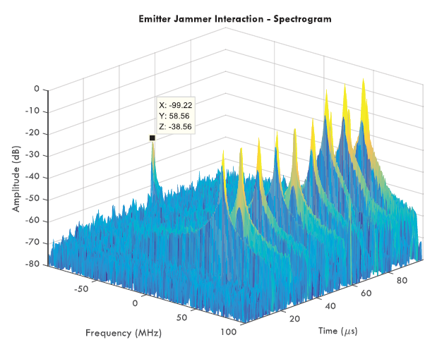
This chapter outlines an example of PathWave System Design (SystemVue) software for performing radar and EW system design and jammer/interferer analysis. Some of the key areas to be discussed include how to implement a radar chirp waveform, design an RF chain for the transmitter and receiver, and perform pulse-compression analysis using fast Fourier transform (FFT) based convolution. Finally, the radar system is tested in the presence of unwanted interference and jamming signals to study the impact of such unwanted impairments on radar performance.
Chapter 4 - Simulation and Verification of Pulse Doppler Radar Systems
Modern radar systems that operate in environments with strong clutter, noise, and jamming require advanced digital signal processing techniques. Direct analysis techniques often fail when designing such complex systems. Although simulation is often used, most simulation tools do not have enough models and integration capability to handle modern radar systems.
This section proposes a solution to this dilemma, a system-design methodology that uses PathWave System Design (SystemVue). Examples will be used to illustrate how advanced pulse Doppler (PD) surveillance radar with moving target detection (MTD) and a constant false alarm rate (CFAR) processor can be designed. To ensure the design works properly, the platform can be connected to instrumentation for system test and verification. This allows users to reduce their system development time and cost, while also decreasing their chances of unexpected system failures late in the system development process.
Chapter 5 - Applying Ultra-Wideband technology in Radar and EW Systems
Ultra-wideband (UWB) radar has become increasingly popular in both commercial and defense industries. They offer several advantages including high accuracy for target detection, good precision for penetrating radars, and low cost for combining radar and communication systems. UWB radars can pass through walls and other obstacles for geolocation/positioning and can support multipath immunity and frequency diversity with minimal hardware modifications.
Modern UWB radar systems often operate in unpredictable environments, with interference, jamming, and other “real world” performance limitations. Therefore, during system development, it is critical for engineers to understand how their actual hardware will perform in these environments.
Chapter 6 - Dealing with the complexity of Phased-Array Systems
Phased array technology is widely used in modern radar systems for rapid multi-target search and track operations, as well as to achieve higher resolution, and better detection performance. Despite these enviable benefits, when developing phased array radar, many issues may be encountered. For modern engineers, that often means a myriad of test challenges, such as finding a way to improve performance while also reducing the high cost of Transmit/Receive (T/R) modules with Direct Digital Synthesizers (DDSs), digital-to-analog converters (DACs), and Analog-to-Digital Converters (ADCs). Addressing these challenges demands an appropriate method of designing and testing phased-array radar systems; one that streamlines the R&D lifecycle so that faster, cheaper, and better phased-array radar systems can be achieved.
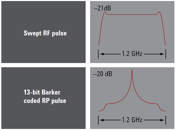
Chapter 7 - Generating Signals for Radar and EW Design and Verification
Modern radar systems use more complex signal formats working in wide or ultra-wide bandwidths and operating in different frequency bands. As shown in the previous chapters, they also use advanced digital signal processing techniques to disguise their operation and overcome strong clutter and jamming in their environment. Addressing this complexity requires a generation of realistic test signals and system-level scenarios that can be used to create and verify the radar signal processing algorithms. While dedicated hardware simulators and field testing are typically used to generate these test signals, both are costly, time-consuming, and apply later in the design process. This chapter presents a less expensive option for generating test signals early in system development.
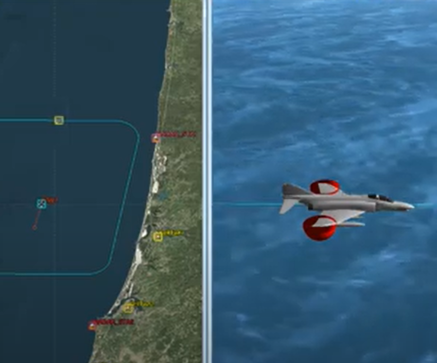
Chapter 8 - Virtual Flight Testing of Radar System Performance
Taking a system-level approach to a complex design often requires upfront integration and analysis, however, it pays in the long run by focusing time and engineering effort on “winning” design strategies. In this chapter, PathWave System Design (SystemVue) is integrated with the STK software from Analytical Graphics Inc. (AGI, an Ansys company) to take advantage of their respective domain strengths to address difficult radar modeling and verification issues.
In addition, the SystemVue Aerospace/Defense library provides radar signal processing/domain IP to render the final details of this system and a friendly interface for modeling and test equipment.
Section 3: RF Component Test and Verification
As radar and EW systems become ever more sophisticated, their demanding performance requirements flow downstream to produce challenging specifications at the component level, with a need to characterize at higher frequencies, wider bandwidths, lower noise levels, and with complex signals
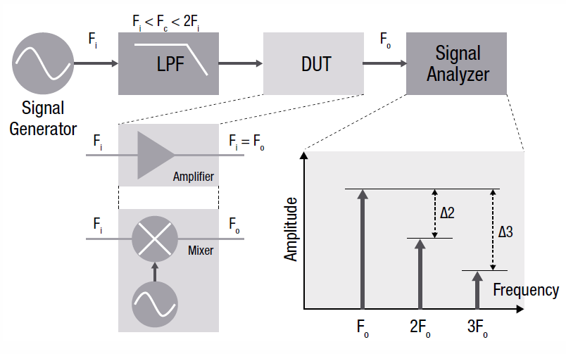
Chapter 9 - Figures of Merit Aid Amplifier Distortion Assessment
Distortion not only degrades transmitter performance but also interferes with other receivers. There are two major types of nonlinear distortion measurements — harmonic and intermodulation distortion. Furthermore, no system offers unlimited gain and it is important to understand the compression characteristics of amplifiers, where the saturation point of the output is an important figure of merit.
Chapter 10 - Determine Your Optimal Noise Figure Measurement Method
Noise, and specifically signal-to-noise ratio (SNR), is a fundamental issue in wireless receivers. High noise levels will limit system performance. A sensitive receiver means you can detect lower-level signals; therefore, a radar can maintain overall performance whilst transmitting at lower power, reducing size, weight, and power requirements. Noise added at an early stage can never be removed, therefore the gain and noise figure at the front-end of a receiver can dominate overall sensitivity. Learn how to characterize your system components and the tradeoffs between the Y-factor method and cold-source measurement.
Chapter 11 - Select the Appropriate Phase Noise Test Solution
Doppler radars determine the velocity of a target by measuring the small shifts in frequency that return echoes have undergone. In actual systems, however, the return signal is much more than just the target echo. If returned signals are decorrelated by the delay time difference, the phase noise from the local oscillator can spread the spectral density of the return signals to mask the target signal, partially or completely. Thus, phase noise on the local oscillator or in any component in the transmit or receive signal chains can set the minimum signal level that must be returned by a target to detectable. Explore the different measurement topologies for absolute and residual phase noise of 1-port, 2-port and 3-port devices, and methods of direct spectrum measurement, carrier removal, and cross correlation.
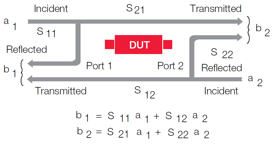
Chapter 12 - Measure S-Parameters with Increased Confidence
Network analyzers characterize radio frequency (RF) devices. Although they began measuring S-parameters, network analyzers have become highly integrated and advanced to stay ahead of the devices they test. Vector network analyzers are extremely versatile instruments that can characterize scattering-parameters (S-Parameters), match complex impedances, make pulsed measurements, characterize multi-port devices, de-embed fixture effects, and more.
Chapter 13 - Characterizing Frequency Translating Devices
Frequency-translating devices like upconverters and downconverters are one of the fundamental components in every RF or microwave transceiver chain and play fundamental roles in the transmit and receive chains of all defense systems, ranging from EW, ECM, ESM, ELINT, and SIGINT receivers, to satellite terminals and transponders, and radar systems. Radar, EW, and satellite RF systems require frequency converters or mixers with specified and well-controlled amplitude and group delay response. These key components present unique measurement challenges because they exhibit both desired and undesired linear and non-linear behavior.
Chapter 14 - Expand Insight into Nonlinear Behavior and Modeling
S-parameters assume that all elements in the system are linear, this approach does not work well when attempting to simulate performance when the amplifier is in compression or saturation, as real-world amplifiers often are. Testing today’s high-power devices demands an alternate solution—one that quickly and accurately measures and displays the device’s nonlinear behavior under large-signal conditions and provides an accurate behavioral model that can be used for linear and nonlinear circuit simulations. Active hot parameters are appropriate for amplifiers where the transistors are pre-matched and are used to verify that the matching is good and there are not any extraneous matching issues. The technique is significantly faster than other methods. Bare transistors, which require substantial impedance matching at fundamental and harmonic frequencies require testing with the nonlinear vector network analyzer (NVNA) and X-parameters - the mathematically correct extension of S-parameters to large-signal conditions. NVNA and X-parameters provide a means to efficiently analyze and design active devices and systems under real-world operating conditions, reduce design cycles by as much as 50%, and providing valuable insight into device behavior with full nonlinear component characterization.
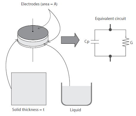
Chapter 15 - Methods for Measuring the Dielectric Properties of Materials
Dielectric property is one of the fundamental electromagnetic properties of materials. It describes how a material interacts with an applied electromagnetic field. Accurate measurements of these properties can provide scientists and engineers with valuable information to properly incorporate the material into its intended. A dielectric materials measurement can provide critical design parameter information for many electronics applications. Numerous techniques are adopted for material characterization and here we provide an overview of the techniques for: Parallel Plate, Coaxial Probe, Resonant Cavity, Transmission Line
Section 4: Radar and EW Subsystem test
The evolution from purely analog designs to hybrid analog/digital designs continues to drive advances in radar system capability and performance. Frequencies keep reaching higher and signals are becoming increasingly agile. Signal formats and modulation schemes—pulsed and otherwise—continue to become more complex, and this demands wider bandwidth. Advanced digital signal processing (DSP) techniques
are being used to disguise system operation and thereby avoid jamming. Architectures such as active electronically steered arrays (AESA) rely on advanced materials such as gallium nitride (GaN) to implement phased-array antennas that provide greater performance in beamforming and beam steering.
Chapter 16 Signal Source Essentials- Parameters, technologies, and methods
Productive and efficient engineering of EW systems requires the generation of test signals that accurately and repeatedly represent the EW environment. Simulation of multi-emitter environments is vital to ensure realistic testing. Simulation for these multi-emitter environments traditionally encompasses large, complex, and custom systems during the system qualification and verification stage. These systems are usually not widely available to EW design engineers as R&D test equipment. EW designers working on optimization and pre-qualification are at a disadvantage in comparison to wireless engineers performing similar tasks. EW engineers often discover the nature and magnitude of performance problems later in the design phase — leading to delays, design rework, and solutions that are not optimale, to perform your own phased array modeling and simulations.
Chapter 17 Measuring Radar and EW Signals
A radar transmitter is the costliest component of the system with the highest power consumption, most stringent cooling requirements, and greatest influence on system performance. There are various parameters which needs to be measured and several options like power meter, spectrum analyzer or signal analyzer. The combination of right hardware and software can offer real insights into these measurements which can help engineers build a robust and accurate setup.
Chapter 18 Testing TR Modules efficiently
Radar, satellite, and electronic warfare (EW) systems utilize a wide variety of microwave modules. Active Electronically Steered Arrays (AESA) is one of the most critical and complex modules of a Synthetic Aperture Radar (SAR). A phased array antenna with an array of antenna elements controls the relative amplitude and phase of signals from these elements to concentrate the energy in the desired direction. The attenuator and phase shifter in each TR module quickly change their states, which enables a phased array antenna to scan the narrow beam very rapidly. Today’s phased-array antennas utilize 100s or even 1000s of antenna elements with TR modules. Their energy can be directed and scanned to multiple positions, which makes them extremely flexible for use in radar, electric warfare, and communication applications.
Chapter 19 Understanding the Techniques for Antenna Testing
Radar, satellite, and electronic warfare (EW) systems utilize a wide variety of microwave modules. Active Electronically Steered Arrays (AESA) is one of the most critical and complex modules of a Synthetic Aperture Radar (SAR). A phased array antenna with an array of antenna elements controls the relative amplitude and phase of signals from these elements to concentrate the energy in the desired direction. The attenuator and phase shifter in each TR module quickly change their states, which enables a phased array antenna to scan the narrow beam very rapidly. Today’s phased-array antennas utilize 100s or even 1000s of antenna elements with TR modules. Their energy can be directed and scanned to multiple positions, which makes them extremely flexible for use in radar, electric warfare, and communication applications.
Section 5: System Level Radar and EW Test
Emergence of 5G and its wide use cases, courtesy the specifications, includes EW as one of the potential adopters. Also, the open architecture, cognitive and adaptive algorithms, software intelligence brings in next level of challenges including cyber security. The deployment of these systems with precision and constant maintenance also requires immense expertise and services.
Chapter 20 Avoiding 5G Coexistence and Effectively Simulating Background Signals
With new bands specified for 5G communications systems, there is now an issue of coexistence, which is radar and satellite using the same or similar frequency bands with 5G. Such coexistence can cause loss of capacity in 5G systems and can even damage sensitive front ends in satellite
ground stations.
Chapter 21 Validating Jammer Effectiveness
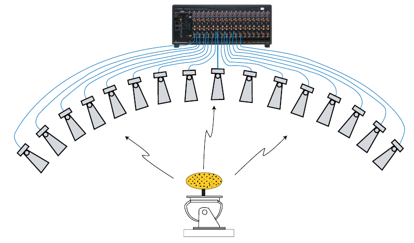
Test systems used to evaluate jammer effectiveness are structured so that each component like channel emulator, signal emulator, radar echo generator, scenario controller, signal generator etc. has a specific function and relation with the System Under Test. Designers of these systems should consider all requirements early in the design and development to avoid any expensive modifications.
Chapter 22 Radar and EW Signal Recording and Analysis
Gap-free recording of a complex RF environment is a practical way to capture elusive and intermittent signals for further analysis via playback and post-processing. This all depends on seamless ntegration between analyzer, recorder, and software to make the raw IQ data meaningful for analysis purpose. With wide analysis bandwidth, low noise floor and gapless recording capabilities a lot of meaningful information can be extracted from massive amount of data.
Chapter 23 Electronic Intelligence
Electronic Intelligence (ELINT) is a subdivision of Electronic Support (ES) within Electronic Warfare (EW). ELINT is concerned with the non-cooperative interception of electromagnetic signals that do not carry communications. Such signals cover all categories of radar, beacons and transponders, jammers, missile guidance, radio altimeters, navigation emissions, and identification systems (IFF). Efficacy is concerned with effectiveness of a radar’s ability to withstand an electromagnetic attack (EA) or to be able to mitigate such an attack. While strictly not a radar signal, identifying and characterizing EA signals is also an essential task. EA encompasses jamming, spoofing (false target generation), and intelligent attack. It is important to note that the scope of EA is wider than jammers alone as many new systems are able to use machine intelligence to generate a sophisticated multi-faceted attack with the objective of fooling the radar and not merely jamming it. This new approach to EA is in response to new low probability of intercept radars, radars that utilize spread spectrum techniques, smart radars using beam management to mitigate EA and multi-static radars.
Chapter 24 Test system calibration and alignment
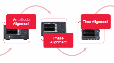
When generating a realistic scenario capable of testing the performance of a modern SUT, some key concepts must be utilized. Initially, we need to look at the system calibration process. First, there is the need for system coherence. Next, we need amplitude alignment, phase alignment, and time alignment to emulate angle of attack, also called angle of arrival (AoA). Once we have a coherent system that is amplitude, phase, and time-aligned, we can use the calibrated system to create a realistic emulation of an electronic warfare electromagnetic environment.
Chapter 25 Field testing, sustainment, uptime-service, and support
The typical aerospace/defense weapons programs can last decades, hence a consistent and reliable performance must be ensured. The sustainment phase of an A/D program makes up most of the program’s lifetime cost, up 70% of the total program cost. However, it is underappreciated and undervalued when key decisions are made during the early stages of the program. These milestone decisions made during the early stages incur upfront costs that are relatively high compared to the rest of the program’s per-incident costs. However, these key decisions also define the rest of the program, including the long-term costs during the sustainment phase.
Chapter 26 Software Testing for Radar & Electronic Warfare Systems
In addition to testing the hardware components of radar and electronic warfare systems, growing importance is attached to testing the software of these systems. Software test automation is a key component of DevOps. Recent years have seen a push towards DevOps across IT systems in both private industry and national defense. DevOps refers to the set of practices that automate processes between software development and operations. The goal of DevOps is to build, test, and iteratively release more reliable software in a faster manner, often involving and complementing Agile methods.
Chapter 27 New Age Requirements of Cyber Security
Connected networks such as air defense and air traffic control are vulnerable to cyber-attacks. Search online and you will find examples of hacking and spoofing that disrupted defense networks rendering them temporarily ineffective, allowing adversaries to gain tactical advantage. Not all hackers have such perilous intent – their motivation may be espionage or simply penetrating a secure system for “fun” as a test of skills and wits. With modern systems becoming increasingly connected, and with regular software updates required for adaptive systems and machine learning, securing your operations against cyber-attacks has never been more important.

Would you like to receive further information, request a demonstration or have one of our applications experts discuss your specific needs?
Complete the form and a Keysight representative will be in contact with you shortly.
List of Acronyms
AAI Air-to-Air Intercept
ACPR Adjacent Channel Power Ratio
ADC Analog-To-Digital Converter
ADS Advanced Design System
ADT Automatic Detection and Tracking
AESA Active Electronically Scanned Array
AEW Airborne Early Warning
AFC Automatic Frequency Control
AFR Automatic Fixture Removal
AGC Automatic Gain Control
AI Artificial Intelligence
AM Amplitude Modulation
AoA Angle of Arrival
APAR Active Phase Array Radar
AUT Amplifier Under Test
AWG Arbitrary Waveform Generator
AWGN Additive White Gaussian Noise
BITE Built in Test Equipment
BSD Blind Spot Detection
BW Bandwidth
CAD Computer Aided Design
CEMA Cyber and Electromagnetic Activities
CFAR Constant False Alarm Rate
COHO Coherent Oscillator
COTS Commercial off the Shelf
CW Continuous Wave
DAC Digital to Analog Converter
DANL Displayed Average Noise Level
DBF Digital Beam Forming
DDS Direct Digital Synthesis
DOA Direction of Arrival
DRFM Digital Radio Frequency Memory
DTM Digital Terrain Model
DUT Device Under Test
EA Electromagnetic Attack
ECC Error Correcting Code
ECCM Electronic Counter-Countermeasures
ECM Electronic Counter Measure
EDA Electronic Design Automation
EIRP Effective Isotropic Radiated power
ELINT Electronic Intelligence
EMS Electromagnetic Spectrum
EMV Electromagnetic Vulnerability
EOB Electronic Order of Battle
EPM Electronic Protective Measures
ESA Electronically Steerable Array
ESM Electronic (Warfare) Support Measures
ETP Equivalent Transmitter Power
EVM Error Vector Magnitude
EW Electronic Warfare
FAR False Alarm Rate
FCA Frequency Converter Application
FCC Fault Collection Unit
FCW Forward Collision Warning
FDOA Frequency Difference of Arrival
FFT Fast Fourier Transform
FM Frequency Modulation
FMCW Frequency Modulated Continuous Wave
FOM Frequency Offset Mode
FPGA Field Programmable Gate Array
FSK Frequency Shift Keying
GCA Ground-Controlled Approach
GPR Ground Penetrating Radar
GTC Gain Time Control
HIL Hardware in Loop
HPA High Power Amplifier
IF Intermediate Frequency
IFF Identification Friend or Foe
IMD Inter Modulation Distortion
ISL Integrated sidelobe level
LNA Low Noise Amplifier
LO Local Oscillator
LPF Low Pass Filter
LPI Low Probability of Intercept
LRU Line-Replaceable Unit
LVDS Low Voltage Differential Signaling
MBE Model Based Engineering
MDF Mission Data File
MFR Multi-Function Radar
MIMO Multiple Input Multiple Output
MMIC Microwave Monolithic Integrated Circuit
MSSR Monopulse Secondary Surveillance Radar
MTD Moving Target Detection
MTI Moving Target Indication
MTTR Multi Target Tracking Radar
NFA Noise Figure Analyzer
NIST National Institute of Standards and Technology
NVNA Non-Linear Vector Network Analyzer
OCR Optical Character Recognition
OTH Over-The-Horizon
PA Power Amplifier
PAR Phased-Array-Radar
PAR Precision Approach Radar
PDW Pulse Descriptor Word
PDF Probability Distribution Function
PESA Passive Electronically Scanned Array
PLL Phase Locked Loop
PNTS Phase Noise Test System
PRF Pulse Repetition Frequency
PRI Pulse Repetition Interval
PRN Pseudo-Random-Noise
PRT Pulse Repetition Time
PSD Power Spectral Density
PSL Peak sidelobe level
PW Pulse Width
RADAR Radio Detection and Ranging
RBW Resolution Bandwidth
RCS Radar Cross-Section
RDF Range and Direction Finding
RF Radio Frequency
RS Ramp Slope
RWR Radar Warning Receiver
RX Receiver
SAM Surface-to-Air Missile
SAR Synthetic Aperture Radar
SDR Software Defined Radio
SFDR Spurious Free Dynamic Range
SIF Selective Identification Feature
SMC Scalar Mixer Calibration
SMR Surface Movement Radar
SNR Signal-to-Noise Ratio
SOLT Short, Open, Load, Thru (calibration)
SPI Serial Peripheral Interface
SSA Signal Source Analyzer
SSB Single Side Band
SSPA Solid-State Power-Amplifier
SSR Secondary Surveillance Radar
STALO Stable Local Oscillator
STAP Space-Time Adaptive Processing
STC Sensitivity Time Control
SUT System Under Test
T/R Transmit/Receive
TBP Time-Bandwidth Product
TDOA Time Difference of Arrival
TDR Time Domain Reflectometer
TMA Terminal Maneuvering Area
TOI Third Order Intercept
TRL Thru, Reflect, Line(calibration)
TRM Transmitter-Receiver Module
TWT Traveling Wave Tube
TX Transmitter
ULA Uniform Linear Array
UUT Unit Under Test
UWB Ultra-Wideband
VCO Voltage Controlled Oscillator
VMC Vector Mixer Calibration
VNA Vector Network Analyzer
VSA Vector Signal Analyzer
VSG Vector Signal Generator
VSWR Voltage Standing Wave Ratio
Acronyms acknowledgement
Publisher: Christian Wolff (Revised by Karina Hoel and Keysight Technologies). Text is available under the GNU Free Documentation License (https://www.gnu.org/licenses/fdl-1.3.html), and the Creative Commons Attribution-Share Alike 3.0 Unported (CC BY-SA 3.0) (https://creativecommons.org/licenses/ by-sa/3.0/) license, additional terms may apply.
Learn more about our commitment to privacy: Keysight Privacy Statement
© Keysight Technologies
© Keysight Technologies